Saturday, February 2, 2013

Transfer Table Staging-Part VI

Continued from Transfer Table Staging-Part V

Just a quick update. The styrene piece I was using to trigger the photo-interrupter sensor had a blunt edge.  This was causing the drawer to stop at two different spots depending on the direction of travel.  One of the forum members at nscale.net recommended that I taper the end symmetrically from both sides so the sensor will be triggered at the same spot regardless of direction of travel.  What a brilliant idea.  It worked beautifully. 

I temporarily taped some track in place and tested this with some hoppers.  Here’s a video. 

I am very excited!  I can’t wait for the rest of the parts to arrive so I can finish this up!

Tuesday, January 29, 2013

Transfer Table Staging-Part V

Continued from: Transfer Table Staging-Part IV

Wow, I can’t believe it’s been more than a year since I last touched this project!  I had to read my own blog to figure out what I posted last!

Anyways, over the past year, I’ve had very little time to work on this and anytime I did so, it was a very frustrating exercise in trying to figure out how I will accomplish what I want.  There are a lot of very simple ways to do this manually.  But I want to use a control panel like so:

Staging Drawer Control Panel

The way this would work is I would have a flip switch that either powers the track, or the staging drawer itself.  So, let’s say that I want to take the train that is currently on staging track 3 out to the layout.  The steps I would follow would be:

  1. Flip the switch to the “Drawer” position.  This would kill power to all the tracks on the drawer plus the approach tracks.
  2. Set the rotary dial to “3”.
  3. Use the In/Out rocker switch to move the drawer.  The drawer will stop automatically when track 3 is aligned with the approach tracks.
  4. I flip the switch back to “Track”.  This kills power to the drawer (so no accidental movements as the train is leaving) and supply track power to ONLY track 3 and the approach tracks.

Same idea when parking a train in staging.

To accomplish this, I used slot style photo-interrupter sensors. I have one of these for each track on the drawer.  There is a small styrene piece that is attached to the drawer which goes through these as the drawer moves.  The key here is that all the circuits are in parallel but only the track that is selected has current on it.  So when the styrene piece slides into place on that photo-interrupter, the sensor is triggered and the circuit is broken, stopping the linear actuator. 

In order to only power the selected track, I simply used a double deck rotary switch. 

Here’s the wiring diagram:

Staging Drawer - Automatic Indexing Wiring Diagram

Here’s how I connected everything together using a breadboard:

Staging Drawer - Breadboard Wiring Schematic

This took me a very long time to figure out, but probably because I’m so clueless when it comes to electronics.  I had to look up what a transistor is on Wikipedia.  It’s that bad.  Smile

A few key learnings:

  • The actuator was way too fast.  The power would cut off when the sensor was triggered but its momentum would keep it moving past the sensor.  I had to use a speed controller to slow down the actuator to about 1/3 of its regular speed which was 1/2” per second.  So you need something that moves about 0.15” per second.
  • It is very important to read the datasheets of the sensors you use.  These are delicate things and I fried about 7-8 of these while trying out various (incorrect) wiring scenarios.  They’re not very expensive, but it adds up and gets very frustrating.
  • Also, don’t try to use the sensors to drive the actuator.  That’s what I had tried initially.  It would’ve made for a simpler design, but the sensors just could not handle the current load required to move the actuator.  The whole thing works like a charm using relays though.
  • Don’t be afraid to experiment, and don’t give up. 

Finally, here’s a video of the entire thing in action.  Apologies for the shaky video and the slurred speech; it was very late when I finally got it to work and I was really excited. 

After this, it’s some cleanup work, and then laying down the TRACK!  YAAY!

Here are some resources I used for this project:

Friday, March 30, 2012

Prototypical Operations on a Small Layout

Life took precedence over the transfer table staging project, and progress on that got postponed for at least a month or two. In the meantime, I had a more immediate issue. I’m about 40% done with the small layout, and it’s gotten to be quite boring watching the trains run around and around. I needed an operating scheme fast to keep the interest alive on that layout. And, it had to be something simple so that the kids can play along. Elaborate switch lists and multiple stop waybills were going to be too complicated.

I tried hard, but couldn’t come up with a realistic operating scheme. So, I decided to look at the prototype for inspiration. Since I needed simpler operations, a branch line would be perfect. I also wanted it to be something that the kids could relate to.  So, I decided to look at present day local railroads located in the Pacific Northwest, preferably in the State of Washington.

After combing the web, I found the following resources to be the most useful:

After combing through most of this, I found that one of the most intriguing short lines was the Puget Sound and Pacific Railroad. The railroad interchanges with both UP and BNSF at Centralia. Its trains run up to Elma where the railroad is headquartered. Here, the line splits into two branches, one going west to Hoquiam and another going north to Bremerton.  The one other junction is the Bremerton junction, just north of Belfair. Click here to see their system map.

The major customers are the lumber companies, waste, food etc.  They also service the Puget Sound Naval Shipyard in Bremerton, and the Bangor Naval Base.

I then started researching the industries that had active spurs (according to Bing and Google maps) on the PSAP lines. Of all the industries, I decided to go with the following (all of which exist unless otherwise noted).

  • Sierra Pacific
  • Weyerhauser
  • CFN Pacific Pride Petitt Oil Co.
  • Olympic Oyster Co. (imaginary)
  • The Three Chocolatiers (imaginary)
  • Cascade Plastics (imaginary)
  • Minder Meats
  • Viking Fence Co.
  • Puget Sound Naval Shipyard
  • Bangor Naval Facility

Of all these industries, only 4 of them would be represented on the layout. The Three Chocolatiers (because, the kids wanted it) and Cascade Plastics (to generate hopper traffic) will have their own spurs. Minder Meats and Viking Fence Co. will be represented with the third spur on the layout, which is a team track.

Ok, now that I had a prototype that matched my criteria, how on Earth was I going to represent that on a railroad that is only 24”x44”?  I knew that I was going to have to reuse much of the track; the same passing siding will need to be two different locations based on where you are on the map. This is the track layout for my railroad:

image

After analyzing the PSAP map and looking at my own layout for hours on end, I came up with the following operating schematic:

image

This is how my schematic maps to the actual PSAP system map:

image

Now, let me show you how that track schematic maps to the actual track arrangement that I have on my layout.  First off, let’s go over the part from the Centralia to Cedarville. This area is quite scenic on the actual PSAP and runs parallel to a river.  Great for my trestle scene.  The tunnel was a stretch, but isn’t everything a bit of a stretch in a project like this? The entire Centralia yard is represented with the short spur on the lower left (which happens to be a cassette dock) and the passing siding.

image

Next is the junction at Elma. The yard at Elma is represented by a single long spur and the passing siding. Trains headed for Hoquiam drop off any cars destined towards Bremerton at the Elma yard and then keep going on the outer loop to cassette staging.

image

Then comes Shelton, where the imaginary Three Chocolatiers is located and the Bremerton Junction where the line again splits into two. The passing siding now takes on its third role as the junction. The inner loop becomes the PSAP line going north to Silverdale and Bangor Naval Base, and the outer loop becomes the line going east to Bremerton. Here the engine can cut the cars destined for Silverdale/Bangor at the passing siding and take the cars destined for Bremerton on the outer loop to cassette staging. Then it comes back to pick up the cars on the passing siding and continue on North on the inner loop.

image

Finally, we reach Silverdale where the most industrial switching will occur. After switching the two spurs at Silverdale, the engine continues on towards Bangor Naval Base on the inner loop all the way to cassette staging.

image

For returning trains, the operation is very similar, but in reverse, with everything terminating at Centralia Yard.

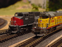
I prepared the following system map to use as reference. This is now hanging above the railroad. What on earth is MKT stuff doing there you might say.  Well, did I mention this layout is mostly for the kids?  Well, the UP Heritage “Katy” SD70ACe happens to be their favorite engine, and the GP40 MKT just looks way too cool.

image

Creating this operating scheme was a very satisfying experience. It just goes to show you that no matter how small your layout is, you can still come up with a very realistic operating scheme based on the prototype. This is possible, even if you didn’t start out with an operating scheme in mind, as was the case here.

Next up, I will cover the extremely simplified car routing system I came up with to support these operations.

Friday, December 2, 2011

Transfer Table Staging–Part IV

Continued from: Transfer Table Staging-Part III

Two days ago, the linear actuator and the power supply arrived and I’m just blown away by how smooth this thing operates. It was relatively inexpensive too. It’s still not a cheap solution for staging perhaps, but compared to other linear motion products out there, the Firgelli Automations stuff was quite reasonable.  Their power supplies were very expensive, and I didn’t need one as powerful, so I ordered a cheaper one from Amazon.

Anyways, tonight I hooked it up to the drawer. It was a bit tough to get the angle right, but I somehow managed. The one problem is the built-in limit switches for the linear actuator go beyond the extent of the drawer, so at the moment if I’m not careful the actuator will rip the drawer right off the wall. It is that powerful. I went with a 150lbs force model because of speed. It’s moving at 0.5” per second and it seems to be a decent speed.

Anyways, enough talk. Best to see something like this in action, so here it is:

Next up is indexing. So stay tuned.